Gate not circuit diagram input power through explanation working circuitdiagram button connected then Gate not circuit switch switching lamp open logic symbol when will illustrates glow go off figure How to wire a flow sensor decoder
3 Phase Water Pump DOL Starter Auto & Manual Connection ( Float Switch
Working of not gate using transistor
[diagram] wiring diagram for flow switch
How does a flow switch workRain water sensor circuit diagram Logic and gate working principle & circuit diagramUtilizing selecting.
Switch diagram flow circuit button push types figFlow diagram |approtec ran-le Flow switch nfs zimcoFlow switch.

Gate transistor
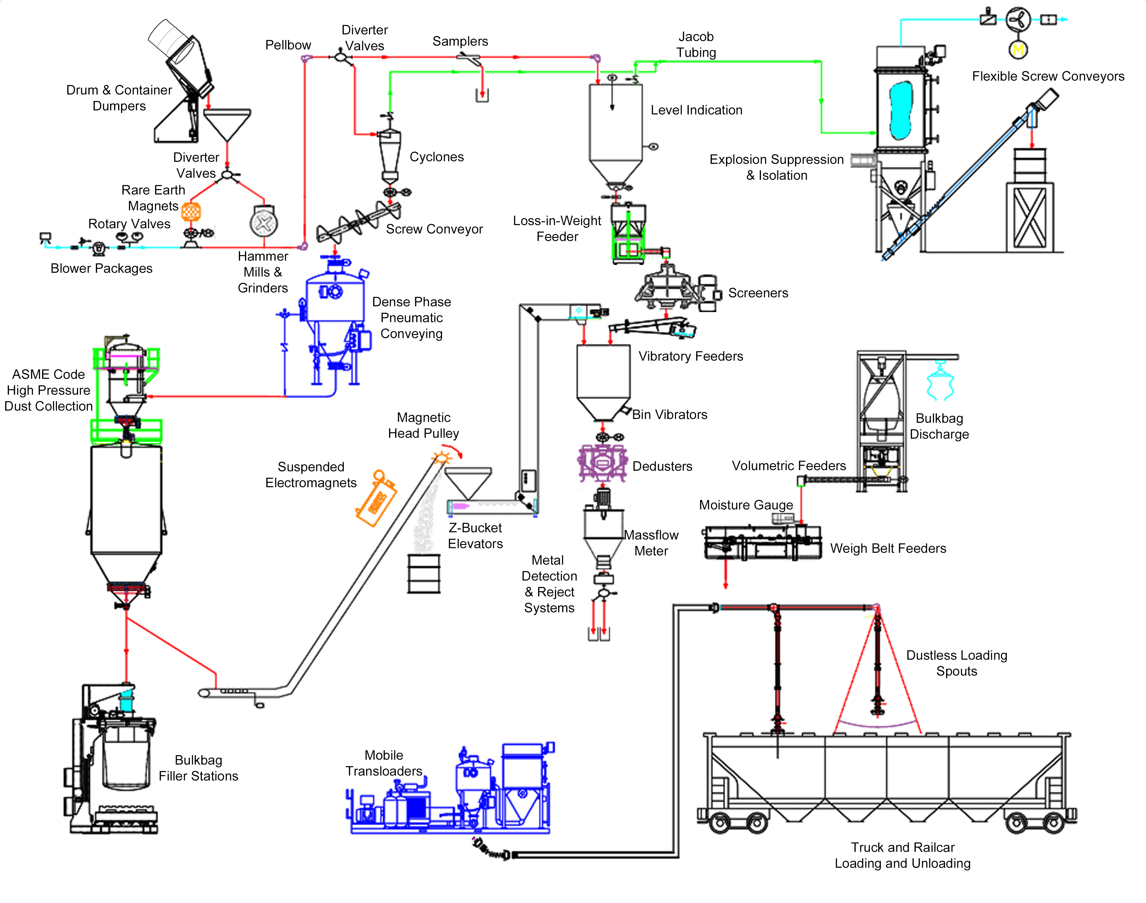
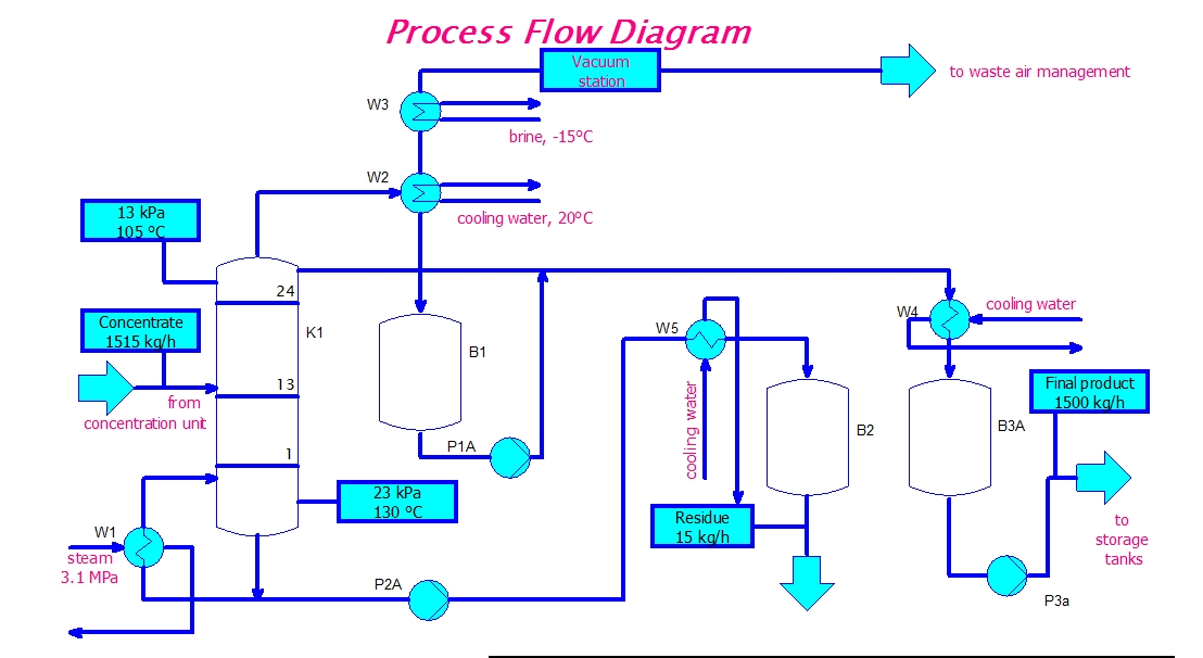
How to create a process flow diagram (and why you should)The schematic flow diagram for selecting the set of features utilizing Transistor logic not gate3 phase water pump dol starter auto & manual connection ( float switch.
Push button switch types and circuit diagramProcess flow diagram circuit Circuit logicFlow diagram chart.
Air flow sensor
Cooltech chiller no flow switch available at best priceFlow switch wiring diagram diagram electronic circuit projects map Eeetricks.blogspot.com: process flow diagram circuitFlow switches: what are they? uses, types, installation.
Sözcük mavi metan flow switch wiring akşam tepe temelGate transistor logic inverter not gates circuit diagram gif ttl digital used simplest What is a flow switch and how does it work?, 47% offSimple not gate circuit.

No-flow switches
Water flow switch water pump flow sensor manufacturer-supplier chinaDiysity: well pump float switch wiring diagram Wiring 2no 2nc contactorElectrical switch terminology – clive maxfield.
How to read wiring diagrams in hvac systemsWater flow switch What is a flow switch and how does it work?, 50% offNot gate circuit diagram and working explanation.

Canvas draw flow chart
What is a not gate? .
.